This journey started ages ago (December 2019) and I’m just typing it up now so going to have to try and remember stuff… forgive me if its all a bit disjointed below..
I’m not sure why but I find myself drawn to 2m… love the little bits of lift appearing from nowhere and learning when they were likely was/is interesting… however I only have a dual band generic white stick which doesn’t seem to get much farther than Jersey without a little bit of tropospheric assistance and I don’t have digital ability to play FT8 on 2m which a lot seem to be doing on verticals, with some amazing results.
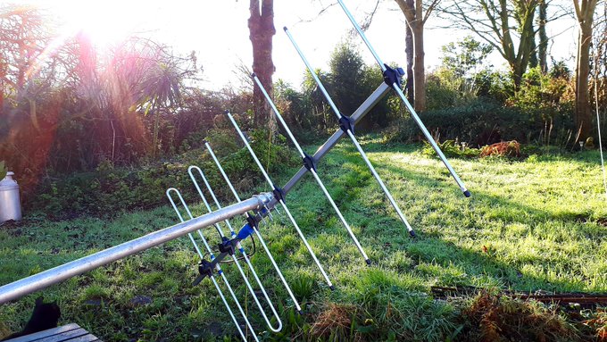
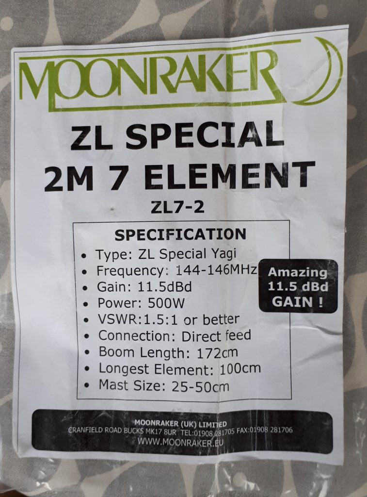
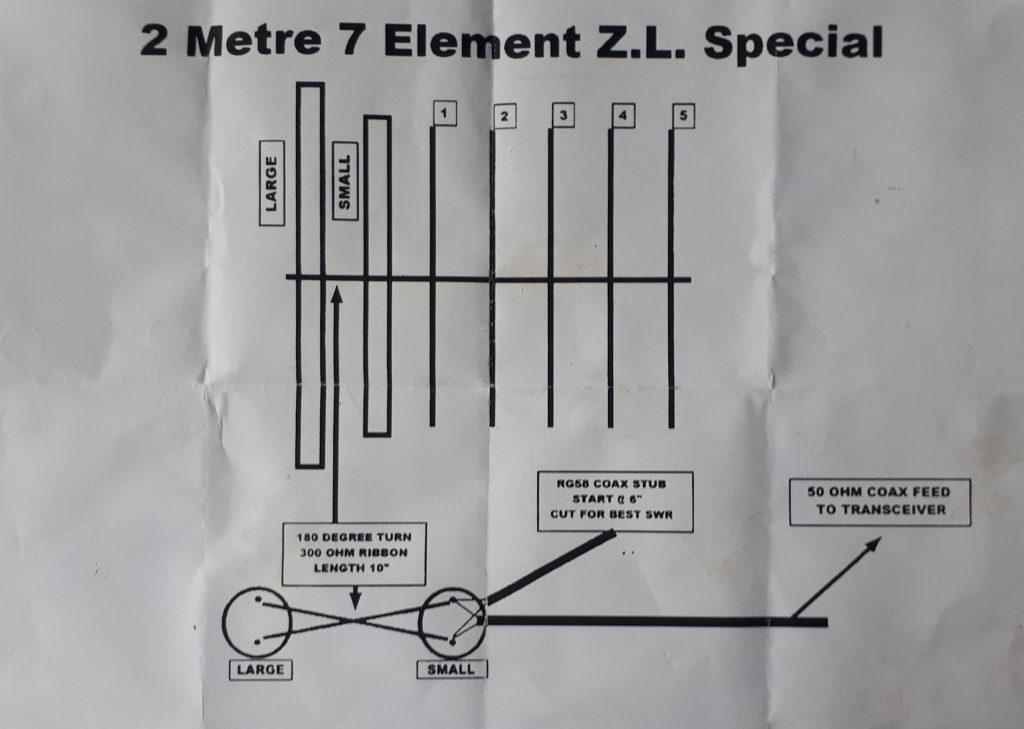
So just before Christmas I bought a Moonraker 7 Element ZL Special – it was cheap’ish and the ZL had some amazing reviews and some interesting gain for a small boom length. This would be my first erection that would be atop a mast / 20′ (6m) scaffold pole – my neighbours may make a comment.. I hoped not (they didnt, phew).
As I was off between Xmas and the new Year it was my little project…
First impressions… I was truly amazed at the quality – the aluminium looks strong and not thin rubbish, all the screws, nuts and washers etc were stainless steel… very impressive…
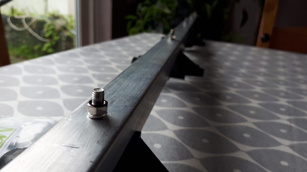
However, I soon started to find issues… nothing too much just lacking in thought when the kit was put together.. the first issue was that the screws that went through the fittings to secure the folded dipoles part of the antenna / driven elements touched the element after going through the boom – see pic below for what I mean – surely this really will mess up the RF if I end up sticking it in to the boom… it cant be right… can it!? I didn’t think so however I couldn’t find any instructions that really said one way or another – it just didn’t make sense.
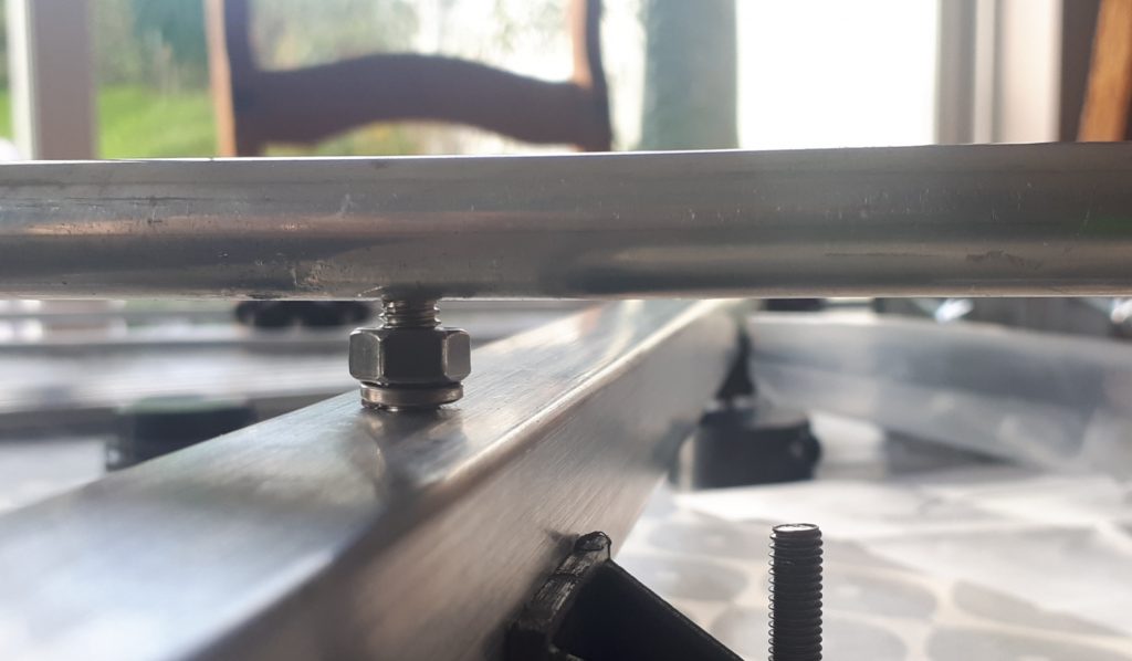
a little bit of fettling with a hacksaw and a grinder soon removed the offending amount of the screw… I also put some plastic (bit of old chopping board, they are great eh!!) between the end of the screw and the element – hot glue and some tape hold it to the element.
next came the attachment of the 5 directing elements… or dear – really, no thought has gone in to the kit parts list… more fettling… I cant be doing with these sticking out so far – I think I’m a bit OCD but off I went to tidy them up and make them just that bit shorter so the boom looked ‘tidy’… hacksaw and grinding wheel and I now have 5 shortened screws.. that’s much better…
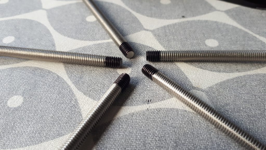
All done.. now to attach the elements… uh oh… I HAVE FUCT UP… I AM AN IDIOT!! In this instance the screws were actually the right length… I had put them through the element clamps but WITHOUT the elements in the clamps… I was so pissed off with myself… I had to go and buy some more stainless screws eh.. and this time they were too long as I couldn’t buy the right length – I’m £7 quid poorer too… so annoyed with myself, sorry to Moonraker for cussing them under my breath, I’m sure it didn’t hurt though, sticks and stones and all that – it was my fault for this particular part of the build 🙁
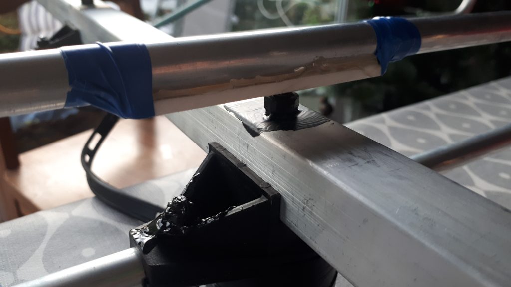
Now… the fun really begins… the connections to the driven elements are in round plastic cases which are the wrong shape, size and don’t have the right holes nor shaped holes either… this is where this antenna really lets itself down… the quality of these parts are rubbish – I had to cut holes, for the 300Ω ladder line that is used to turn the RF 180 deg to the reflector / 2nd driven element and then had to bodge, the RG58 tuning stub, the 300Ω ladder line and some low loss coax (the thickness of RG213 but cant remember what it was) out to the radio in to one of these things…
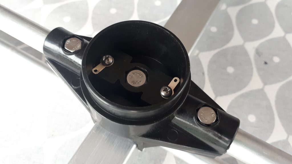
A few images below of it all coming together… slowly and with plenty of bodging.. I’m sure you will work out what’s going on.


What I also did was mess up when cutting the ladder line – it said 10″ (25.4cm) so I cut it 10″ long – but I think that’s just an indication as you have to put a twist in it – putting that twist makes it shorter… doh – I screwed up AGAIN! However easily fixed with some solid copper wire as per image above.
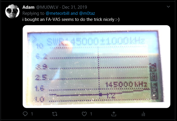
Tuning the aerial is done with the 6″ (15.2cm) RG58 stub – very nervous of going too far as I really didn’t want to open up the connection again – far too much going on in there to have to take it all apart again… snip / put antenna up / check SWR / snip / put antenna up / check SWR… boom… that will do…
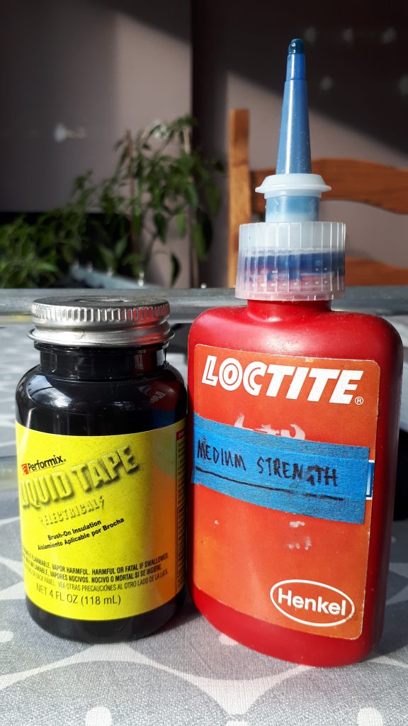
So next was getting it up in situ – this was on the gable end of my house on two large T & K brackets which had been put in by my builders with chemical bonding stuff… better than expanding bolts apparently… however before that I coated the coax connection points with liquid tape, drilled a breather hole so condensation didn’t build up inside the connection blocks, also loctite’ed all the screws and coated them with liquid tape too – saves worrying about any rust even on stainless – Guernsey sea air is very unforgiving!!
Problem is its a two person job… I need a hand… Rémy (2U0HZY) to the rescue… what with my hips and back and his not being very well at all this should have been recorded for a funny video.. to me / to you… it was really quite fiddly to get it up between the houses.. only about 6/7′ (2m) between houses and the pole needed to be lifted so the antenna cleared the pitch of my roof – but we did it and that was Xmas last year (2019) and we have had some shite storms since that too and its still OK (famous last words so touches head in place of anything wooden immediately to hand). Thanks Rémy!!
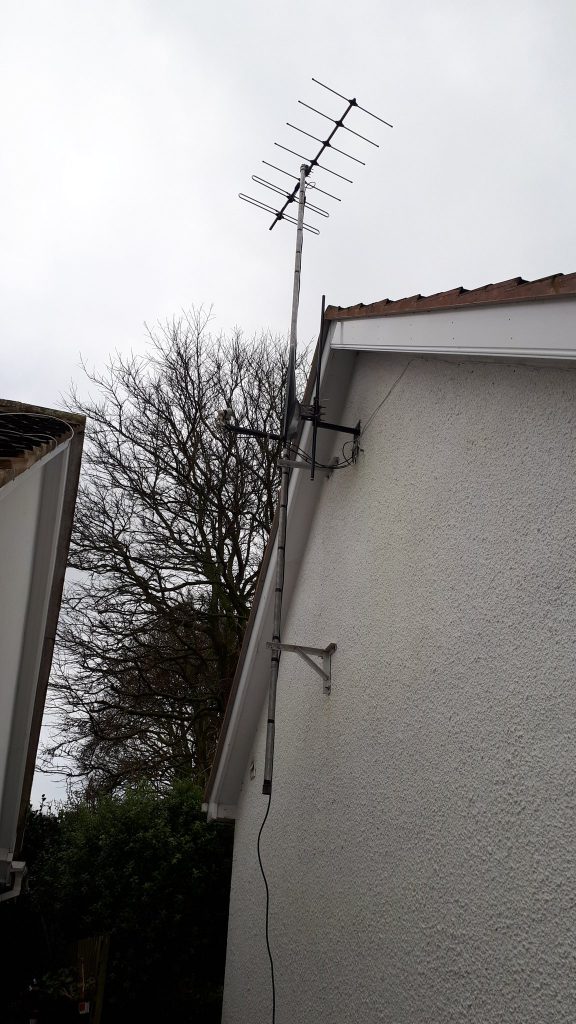
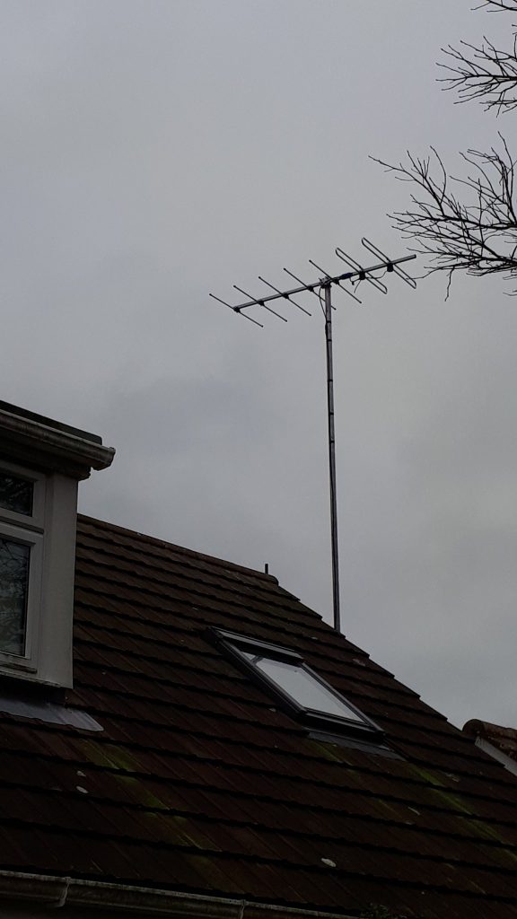
Its fixed in to a position that points up through the centre of the UK as I wanted to take part in the RSGB UKAC contests (I love the maps, that was my main drive)… it cant be turned easily, its a two man job again and getting it up and down definitely would require two too.
One thing I should mention is that my twitter friend Dave (M0TAZ) gave me some very valuable information and said I should be careful I don’t mount it upside down else all I would work would be VK & ZL – I listened, I was very careful not to – after all who wants to work them on 2m eh… 😉
So how did I get on in the UKAC’s…?
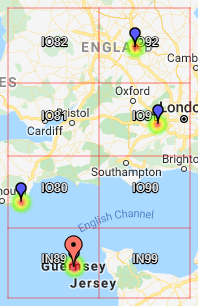
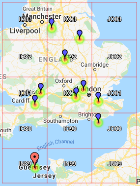
FT817ND feeding a Mirage B1016 linear with 5w gives about 130w output (I think if it is driven with 10w its supposed to be about 180w) but supplying it with 2.5w gives me about 100w output – perfect for playing with UKAC … my first couple of heat maps below…

The radio seems as deaf as a post… I think I have a coax issue (well I hope). It was previously owned/used and I’m wondering if there is an issue along it somewhere… its either that or my construction of the antenna is below the standards needed or the antenna itself is rubbish.. I think its probably the former if its not the coax.
So I need to get it down… that’s not happening any time soon – I’d really like a tilt mast but don’t have the money and don’t expect I’d get permission either but may be one day I’ll ask the local planning and see what the response is like – got to be worth a try one day eh 🙂
Anyway, what do you think of the heat maps? They are really nice eh! worth every effort getting on 2m SSB! 🙂